Analysis on Vibration Performance of Grid Couplings
- 1. Analysis on deformation of nonlinear grid couplings
- 2. Analysis on the vibration performance of nonlinear grid couplings
- 3.Conclusion
Nonlinear grid couplings have wide application. In general, they are used in mechanical transmission systems which have big torques and changed torsional rigidity. With the aid of nonlinear theory, we can research the vibration performance of nonlinear grid couplings in belt conveyor system. In this system, grid couplings can always maintain sufficient flexibility at any time, slight or strong vibration. We can study the amplitude-frequency characteristic of harmonic excitation of a nonlinear grid coupling when the coupling resonant once the frequency of system close to the excitation frequency. This can make necessary theoretical preparations for design and further study of the nonlinear grid couplings.
1. Analysis on deformation of nonlinear grid couplings
The teeth flank of a nonlinear grid coupling is curved. Supposing that the peripheral force goes through one side of half circle spring is P, as shown in figure 1. The distance a is calculated from the partition surface of the spring in grid coupling to the contact line of spring and teeth plank. It decreases along with the increase of load P.
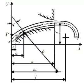
Figure 1. The calculation diagram of a grid coupling on curved supporting raceway
c. Clearance between partition surface and rim edge.
s. The distance from partition surface of rim to the outer end of teeth plank.
m.The distance from partition surface of rim to the center of curvature of supporting raceway.
ρ. Curvature radius of supporting raceway.
l. Straight segment length of half circle spring.
φ.Torsion angle of the coupling.
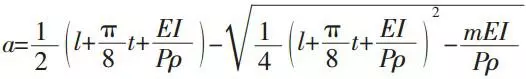
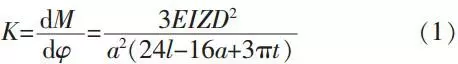
The relationship between P and a can be derived from the common tangent of a touch point, where the line section of spring and the supporting raceway of teeth plank meet with each other. Thus we can get the following formula:
In this formula:
E: The elastic modulus of spring;
I: Inertia moment of spring cross section;
t: Pitch of half circle spring.
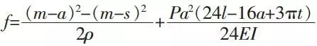
Under the action of load P, the deflection of half circle spring is:
The torsion angle of a coupling is:
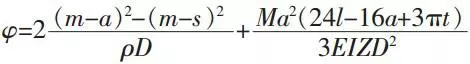
In this formula:
M:Torque that act on a coupling.
The rigidity of a coupling is:
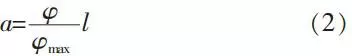
When a=l, φ= φmax, it can be approximately calculated as:
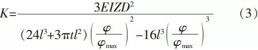
Taking formula (2) into formula (1), and you will get:
To simplify, import mark A=8l+πt and do series expansion to formula (3):
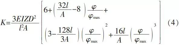
From formula (4) we can get the rigidity of a coupling has nonlinear characteristic. For facilitate the discussion, we express the rigidity as:
2. Analysis on the vibration performance of nonlinear grid couplings
Figure 2 is the transmission system of a nonlinear grid coupling. It is shown that the excitation torque, Td cos (ωt+φ), is added to the driving shaft of a coupling. The driven shaft output at constant torque. The rigidity is nonlinear. According to the theorem of moment of momentum, torques on the both sides of a coupling are balanced so that we can get the differential equation of torsional vibration in the system:
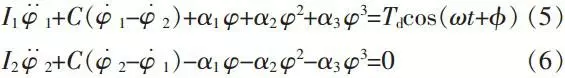
In these formulas:
I1, I2: Equivalent moment of inertia of the coupling driving/driven wheels.
φ1, φ2: Intersection angles of coupling driving/driven wheels.
C: Viscous damping coefficient of the coupling.
Ω: Excitation frequency.
Figure 2. Schematic diagram of coupling transmission system
We can get formula (7) from formula (5) and (6):
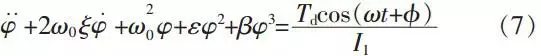
And the linear damping ratio will be:
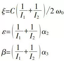
In this formula:
ω0: The frequency of free vibration.
Applying harmonic balance method to solve the equation (7), and we can take the periodic solution of corresponding linear system as a kind of formal solution to the nonlinear system.
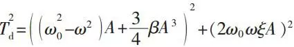
Then, substituting formula (8) to formula (7) and eliminating the higher harmonic terms. What’s more, trying to set the coefficients of cosωt in both sides of equation equal to each other. Supposing that the system frequency is close to the excitation frequency, then the amplitude-frequency characteristic of this transmission system will be:
According to the conditions of system, the parameter values are ξ=0.04, α1=0, β=0.2, Td=1 and ω0=1. On this basis, we can use Matlab for calculation and get results as shown in figure 3. This curve will in accordance with the traditional system amplitude-frequency curve of nonlinear rigidity which containing damping and cubic terms once the value of β is bigger than 0.
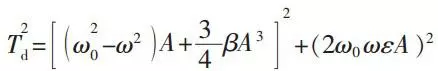
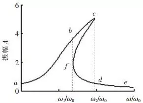
Figure 3. Amplitude frequency curve of coupling harmonic excitation
For forced vibration of linear system, the continuous change of excitation frequency only result in continuous change of response amplitude. Nevertheless, for nonlinear system, the response amplitude rises along with the excitation frequency (as shown in figure 3, following the curve a-b-c). When the amplitude reaches the place of c, any slight increase of frequency will make it drop from c to d. On the contrary, when the excitation frequency increases continually, amplitude will move along the curve e-d-f. When frequency reaches ω1, amplitude will reach f. Then, any slight decrease of frequency here will make the amplitude zooming from f to b. Because of jumping phenomenon, the continuous change of amplitude under the affect of frequency will not be no longer valid. According to above analysis, it is known that thanks to the application of nonlinear grid couplings, the system amplitude will not increase indefinitely when the excitation frequency is close to system frequency.
3.Conclusion
Above analysis shows that using curved tooth profile in the design of coupling teeth planks can endow the rigidity with nonlinear characteristic. Known from the amplitude frequency curve, the frequency of free vibration has something to do with its amplitude. Employing nonlinear grid couplings can adjust system amplitude automatically to decrease the vibratory action and get rid of system vibration and shock.