Installation and Adjustment of Grid Couplings
The coupling having small specification has clearance fit with shaft extension, so the coupling is fixed vertically to keyway by fixed screw; And coupling having large specifications has interference fit with shaft extension, it needs hot charging.
For coupling whose axle hole has interference fit with shaft extension, the surface of hub, axle and key should be checked before installation. Rags and bumping are unallowable. All of parts should be cleaned. The bottom of hub keyway should be coated with appropriate sealant to ensure no oil leakage; If axle hole has clearance fit with shaft extension, heating hub which has clearance fit is not allowed. When installing hub, axle and key, axial fixed screws should be tightened up.
Because axle hole has interference fit with shaft extension, hub needs to be heated. However, maximum heating temperature should not exceed 130℃. For example, if heating temperature is over 200℃, sealing elements can be damaged. Using oven, blow lamp, induction heater or oil bath can heat hub. If heat hub bore directly, steady motion should be maintained, in case of overheating in somewhere.
Notes: before install or maintain the coupling, shut off the start button, and loading from actuating devices also should be removed. If use oil to heat, oil temperature should be higher than 135 ℃, operation cannot carried out in flammable environment or near inflammables. The flashing point of oil must be higher than 177℃. Hub cannot be placed directly under the bottom of vessel. A piece of iron should be placed under the bottom of vessel. Then hub is put on the iron to heat.
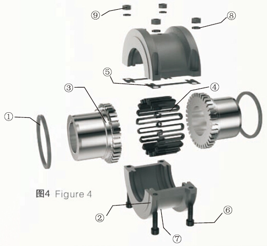
For exploded view of couplings, please refer to figure 4.
1.Seal
2.Shell
3.Wheel hub
4.Spring
5.Spacer
6.Bolt
7.Lubricated plug
8.Sealing gasket
9.Bolt, Sealing gasket
Installation Steps
1. Assembly the seal element and wheel hub, as shown in figure 5.
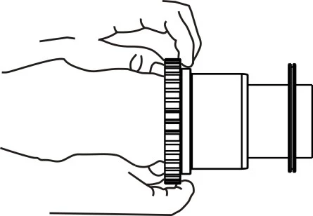
Figure 5
First of all, shut off start button and remove the load from the driving device. Use uninflammable solvents to wipe all of metal parts and two axles which need to be connected. Then, fitting surface of axles is coated with lubricating grease, which needs to be installed with hub. After that, a layer of grease is coated gently on sealing ring. Put the seal ring on the shaft before wheel hub assembly. If it is clearance fit, heating is unnecessary; If it is interference fit, heat the hub according previous description. Then, install wheels hubs on the corresponding shaft, except for other explanations. In general, the hub face is flush with the shaft end. If it is clearance fit, fixed screws need to be tightened up after assembly.
Adjustment and alignment (figure 6).
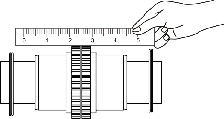
Figure 6
To ensure the normal operation of the coupling, expected working performance and service life, when installing the coupling, proper adjustment is necessary so that two shafts connected with couplings have high coaxiality. The relative displacement of two axes can be measured by using various tools, such as rulers, feeler gauges and dial indicator.
As shown in figure 7, use thickness gauge and ruler to measure the outer edge of the coupling and end face or shaft extension. Then, adjust repeatedly until offset of two orthogonal planes is lower than allowable value. For larger coupling, in general, measure the offset of two orthogonal planes firstly, then work out the direction of relative displacement and size. Adjust and align. For figure 6(a), the approximate value of angular displacement is Δα=(δ2-δ1) / D.
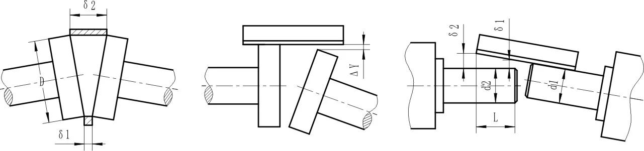
Figure 7 (from left to right are figure 7a, 7b and 7c respectively)
In figure 7, use a feeler gauge and ruler to measure relative displacement of two axes.
(a)Measured with a feeler gauge
(b)Measured with a ruler
(c)Using ruler measure shaft extension
For figure 7 b and 7c, The relative radial displacement and angular displacement of two axis are
ΔY=δ1- 0.5(d1 – d2)
Δα=(δ2-δ1) / L
Using dial indicator can improve accuracy of measurement. As shown in figure 7, measure the outer edge of flange in coupling and the relative deviation of end face.
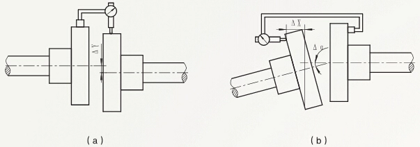
Figure 8
In figure 8, use a dial indicator to measure the relative displacement of the two shafts.
(a)Measuring the outer edge
(b)Measuring end face
Adjust relative radial displacement of two shafts in the vertical plane. Compensation washers are general adopted, and thickness consists of a set of 0.05, 0.1, 0.2, 0.4, 0.2, 0.4, 0.8mm, etc. Choosing relevant thickness should be based on adjustment amount. For reliable adjustment and improving alignment accuracy, adjusting face should be cleaned up at first. Scrap iron and rag are eliminated to increase contact area. Bevel washers are used to adjust relative angular replacement in vertical plane.
The coupling may generate additional relative displacement, due to temperature distortion or load deformation during operation. So the relative displacement between two shafts should be less than the allowable relative displacement of coupling, after adjustment. In general, it should be reduced by 1 to 2 times.
After adjustment, in order to ensure accuracy of adjustment or without readjustment, locating pin can be used to fix relative position of parts. The accuracy of alignment of two shafts after adjustment is shown in table 2.
| Relative displacement | Adjust without gaskets | Adjust with gaskets | |
| General precision | Senior precision | ||
|
Radial displacement Δ Y mm |
0.7-1.4 | 0.3-0.7 | 0.05-0.15 |
|
Angular displacement Δ α mm/mm |
0.6/100 | 0.6/100 | (0.05-0.25)/100 |
|
Axial displacement Δ X mm |
Axial position ±3 (No control unit) | Axial position ±0.1 - ±0.5 (Control units are needed) | |
Table 2, the accuracy of alignment of two shafts after the adjustment.
Notes:
①When the size of the coupling is large, adjust the low accuracy, and choose the maximum value of coefficient in the table.
②In fact, if adopt precision measuring tools through careful adjustment, the error of centering is much smaller than the values in the table after adjustment.
Adjust and ensure these dimensions in the allowable range of coupling installation. Tighten bolts. Check centering after fixing substrate. Allowable deviation of various specification products is shown in table 3.
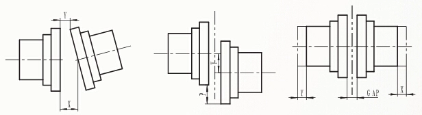
In general, data needing adjustment are follows:
*Angular deviation----Angular deviation embodied in the figure below, the X dimension minus Y dimensions.
*Parallel Offset-----Parallel Offset is P value as below figure, the centerline distance between two wheel hubs.
*Floating ends-----Floating of ends is the axial floating distance of wheel hub inside the outer shell.
Angular deviation Parallel Offset Floating ends
In table 3, the unit is mm.
|
Model |
Install limit | Working limit |
Tightening torque of shell bolt Nm |
Allowable speed rpm |
Grease quantity Kg |
||||
| Max P | Max X-Y |
Gap |
Max P | Max X-Y |
The max floating of two sides 2XG |
||||
| 1020 | 0.15 | 0.08 | 3 | 0.3 | 0.25 | 5.33 | 11 | 4500 | 0.03 |
| 1030 | 0.15 | 0.08 | 3 | 0.3 | 0.3 | 5.03 | 11 | 4500 | 0.04 |
| 1040 | 0.15 | 0.08 | 3 | 0.3 | 0.33 | 5.36 | 11 | 4500 | 0.05 |
| 1050 | 0.2 | 0.1 | 3 | 0.41 | 0.41 | 5.38 | 24 | 4500 | 0.07 |
| 1060 | 0.2 | 0.13 | 3 | 0.41 | 0.46 | 6.55 | 24 | 4350 | 0.09 |
| 1070 | 0.2 | 0.13 | 3 | 0.41 | 0.51 | 6.58 | 24 | 4125 | 0.11 |
| 1080 | 0.2 | 0.15 | 3 | 0.41 | 0.61 | 7.32 | 24 | 3600 | 0.17 |
| 1090 | 0.2 | 0.18 | 3 | 0.41 | 0.71 | 7.26 | 24 | 3600 | 0.25 |
| 1100 | 0.25 | 0.2 | 5 | 0.51 | 0.84 | 10.9 | 35 | 2440 | 0.43 |
| 1110 | 0.25 | 0.23 | 5 | 0.51 | 0.91 | 10.9 | 35 | 2250 | 0.51 |
| 1120 | 0.28 | 0.25 | 6 | 0.56 | 1.02 | 14.12 | 73 | 2025 | 0.74 |
| 1130 | 0.28 | 0.3 | 6 | 0.56 | 1.19 | 14 | 73 | 1800 | 0.91 |
| 1140 | 0.28 | 0.33 | 6 | 0.56 | 1.35 | 14.5 | 73 | 1650 | 1.14 |
| 1150 | 0.31 | 0.41 | 6 | 0.61 | 1.57 | 15.7 | 73 | 1500 | 1.95 |
| 1160 | 0.31 | 0.46 | 6 | 0.61 | 1.79 | 16.3 | 73 | 1350 | 2.81 |
| 1170 | 0.31 | 0.51 | 6 | 0.61 | 2.01 | 15.7 | 147 | 1225 | 3.49 |
| 1180 | 0.38 | 0.56 | 6 | 0.76 | 2.26 | 18.2 | 147 | 1100 | 3.76 |
| 1190 | 0.38 | 0.61 | 6 | 0.76 | 2.46 | 15.7 | 147 | 1050 | 4.4 |
| 1200 | 0.38 | 0.69 | 6 | 0.76 | 2.72 | 15.7 | 260 | 900 | 5.62 |
| 1210 | 0.46 | 0.74 | 13 | 0.91 | 3 | 25.9 | 260 | 820 | 10.5 |
| 1220 | 0.46 | 0.81 | 13 | 0.91 | 3.28 | 29.2 | 405 | 730 | 16.1 |
| 1230 | 0.46 | 0.81 | 13 | 0.91 | 3.28 | 29.2 | 405 | 680 | 24.04 |
The installation of grid coupling, figure 9.
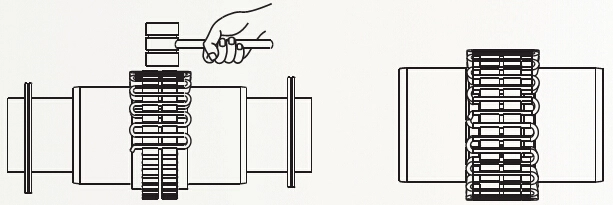
Figure 9 and Figure 10
Before the install the spring, use No. 2 lithium grease to fill the separation distance between hub and groove.
Buckle the spring into the alveolar cavity of hub of coupling. Use soft hammer to knock. When spring is made up of two or more sections, make all of the fracture ends toward in the same direction when in installation, as shown in figure 9.This will ensure the spring contact correctly with boss of shell.
Inject greases into springs and their surrounding as much as possible. Scrape greases which overflow the thickness of spring.
Cover installation, figure 11
Place the seal ring on the appropriate position of the wheel hub, and then embedded into the groove on the half cover below.
Install the sealing gasket in the connector of the two halves. Then close of two halve shell and use bolts to tighten and assemble.
Notes: The corresponding match mark in the two half shell (bosses) should be at the same side after installation. Figure 12.
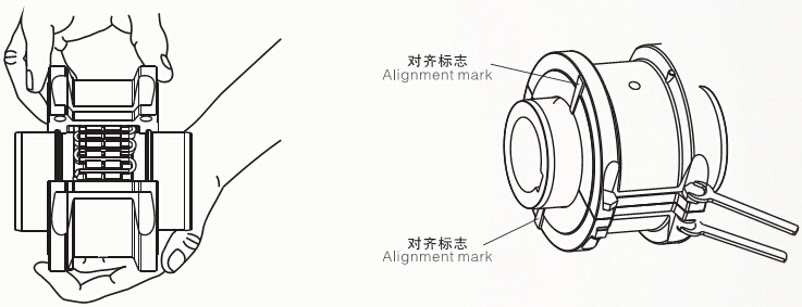
Figure 11 and Figure 12
Check again after installation. Before the formal operation of the coupling, make sure all parts have been installed correctly, closely connected with the coupling and oil plug has been installed inside oil filler hole.
Bolt tightening torque as shown in table 2.
How to remove and replace the coupling.
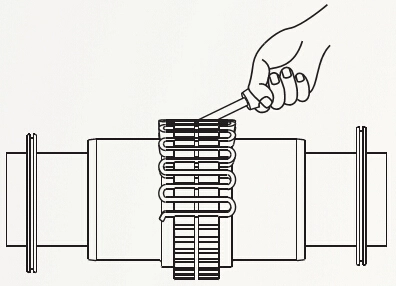
When remove and replace the coupling or spring, disassemble the bolts and remove the cover at first. Start from the fracture end of a spring with a flat mouth screwdriver. Insert the flat mouth screwdriver into the spring. Then pry the spring out slowly in the form of radial, alternately from side to side, to dismount the spring. Figure 13.
For more information concerning grid couplings, please refer to the following articles:
Structure and Application of Grid Couplings
Structural Types of Grid Couplings
Model Selection of Grid Couplings
Rapid Cooling Setup and Connection of Grid Couplings
Carrying and Storage of Grid Couplings
Usage and Maintenance of Grid Couplings
Basic Info for Model Selection of Grid Couplings